With this fitting at the top of the dome, I should have even a little but more room for components than I did with my previous mod. This is because, there are less port extenders needed and no SSD is required at the bottom of the dome. It will still be tight, but I have some wiggle room to address the problems that I brought up in my previous post. Taking them one at a time:
While 12V are readily obtainable from the PSU, the problem is that the PSU is always on. So, the fan will spin as soon as the computer is plugged in, no matter if the computer is on or not. As the computer does not have any 12V out, I will have to use some kind of switch. Luckily, the PSU comes natively with a "switch". The PSU relies on the motherboard to downconvert 12V to 5V then feed 5V back to the PSU to turn on the 24V line that powers the monitor's backlight. Although there are many other ways to do this, I went with an elegant solution using what I had available. Keep in mind this is not the only peripheral that needs power. The optical drive requires 12V and 5V in either a molex or SATA power connector. Luckily, I had a very small 20 pin PICO power supply with a WIDE INPUT range up to 24V. (Not all PICO PSUs can accept 24V, may sure before you connect). I spliced the PWR input to the Green wire of the PSU (24V) which connects to the Inverter Wires as well. I connected the ground to a native PSU ground. As this is a standard 20 pin ATX based PSU, it won't work without a motherboard unless you ground the On Pin. I have it connected to a switch, but will likely just leave in a wire, allowing the PSU to turn on as soon as it receives 24V DC input from the native PSU. This produces the necessary 12V and even a 5V and has both a Molex and SATA power cable out. I connected the Molex to the Fan (you only need the 12V line and ground), and the SATA to the optical drive. Now we the peripherals will only turn on when the motherboard itself is turned on.
![]() |
| The Bypassed Power Switch |
3) Power Switch: I did not want to damage the board, so I simply threaded small wires between the onboard switch and its solder points. I did this to the front right and back left corners. This was then wired to the case switch at the bottom of the dome. These can be easily removed in the future if this board is ever repurposed. In addition this does not effect the functionality of the original switch in any way.
The case switch I use is from my previous mod. Modeling clay was used to secure a momentary switch directly behind the peg that protrudes from the back of the plastic power button on the back of the iMac dome.
4) Audio: I am sticking with the Turtle Bay USB Audio solution from my last mod. This allows for a standard 3.5mm audio jack out and also supports a 3.5mm Microphone in. I have it wired to the microphone in the LCD housing.
5) Bluetooth: I have not found anyone who has had success with any half height mini PCI-E that supports Wifi and Bluetooth with Mac OSX. So, I am simply going to keep my very small USB bluetooth solution.
6) Optical Drive: I am using a DVD Burner that gets power via the PICO PSU discussed in #2. The connection to the mobo is via a SATA to USB 2.0 adapter cable.
![]() |
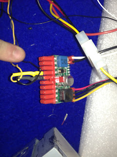
| 12V to 19V DC-DC Upconverter |
7) Power: While the option of splicing the AC to the to the existing AC plug with the NUC's powerbrick is not a bad one, it is somewhat of a waste of the 180 watt PSU that already exists in the machine. Not to mention that I'm already including a second PSU (which is really being used only as a downconverter here). The NUC requires 19V at (at least) 3.7A and the PSU is only supplying 12V (can't use the 24V because its only on with 5V from the motherboard). Luckily, 19V is the typical notebook operating voltage and therefore upconverters are available. Though there is a much smaller selection than for more common voltages (24V, 12V, 5V etc). Many different shapes an sizes are available. I got one in a familiar shape on ebay from a Chinese manufacturer for $20. Its relatively small ( I may remove part of the heat sink surrounding it) and is a 12V DC to 19V DC upconverter at 4A. This is exactly what is required and works flawlessly.
![]() |
| The Upconverter connected to PSU and NUC |
The Upconverter gets 12V and Ground in from the Native PSU and sends 19V out. I had a broken Laptop AC power adapter that had a DC input that perfectly matched the power in plug on the NUC. The positive is the inside peg and the negative is the outer part. Using a multimeter I ensured which wire was which and connected this to the power supply via the up converter.
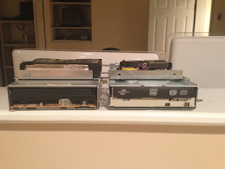
The Fit Test:
![]() |
| The Secured NUC Motherboard |
On a side note, I used a rubber sleeve to cover the drive cage where the NUC will go. After some guess and check, I determined the place where the NUC and USB connectors seemed to fit the best. To test fit, I used twist ties that went through the screw holes in the grooves intended for the HD and then through the motherboard screw holes. These will be replaced with plastic locking ties to secure the motherboard in place.
One thing to make sure of is that the wifi antennae which goes through the metal faraday cage (Wifi signal will be severely reduced if the antenna is within the cage) is connected to the wifi card before the board is secured.
Build Pics:
![]() |
| A Mess of Wires, But A Working Mod |
![]() |
| Video and Audio Test |
![]() |
| Motherboard View |
![]() |
| About This Mac Screen |
Remaining Issues:
Obviously, there is a lot of cable management to do. This will get much simpler once connections are directly soldered (connectors removed and alligator wires eliminated). As I technically have more room at the bottom of the dome than the previous mod (also had a DC converter and a PICO PSU to deal with), I do not believe this will be difficult to fit. The wire management, however, may be more involved.
There will a paucity of ports. A 3.5mm audio out, a few USBs, and not much else. If I had to do it over, I probably would not have bothered spending the extra money on the Thunderbolt equipped version. There are so few available peripherals and there are so overpriced that I can not even test this. Perhaps this is somewhat future proofing, but I would imagine there will be further upgrades to this board before thunderbolt actually takes off (if it ever does). That said, I would not have bothered with an ethernet extender anyway. I've learned with this that the more you do, the more that can go wrong. I am more than happy to keep it simple. I also have the option of adding a powered USB hub with the 12V lines in the PSU. Unlike my previous mod which was very close to its power maximum, this should have room to spare.
Concluding Thoughts:
Untili I have it assembled and have worked with it for a while, I'm cautious about speaking too soon, but I am very optimistic about this project. Although to Core i5 Sandy Bridge to a Core i3 Ivy Bridge may seem like a lateral move, this board is simply a better fit. Its lower power, quieter, and everything onboard works. The incorporation of the native PSU while keeping the optical drive makes this virtually indistinguishable from the original 20" iMac G4.
Hopefully will finish soon! Thanks for reading.


 2) The Fan: The directional fan is connected to the heatsink and I did not want to remove it. I also wanted to keep the case fan. Apple's connectors and colors are completely backwards from industry standards (Black is 12V, Red is Ground and the fan out is a 3pin Male connector, not Female). The fan is also somewhat loud and old, so I decided to replace it. I bought a Antec 92mm fan that had a molex out (there is no case fan output on the board). There is a sense pin that I won't be using. Because I won't have software fan control, I got a model with a 3 speed setting. I put it on medium to reduce noise and may extend the controller to the back ports or simply leave it on this setting.